

MIS231-MIS234 QuickStep - NEMA23 Programmierbare integrierte ServoStep-Motoren mit Closed-Loop, Ethernet, Multiturn-Encoder
|
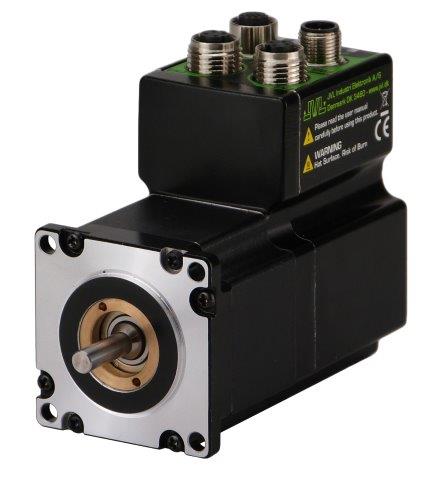
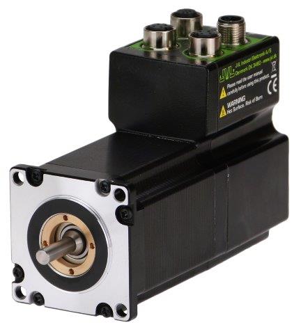
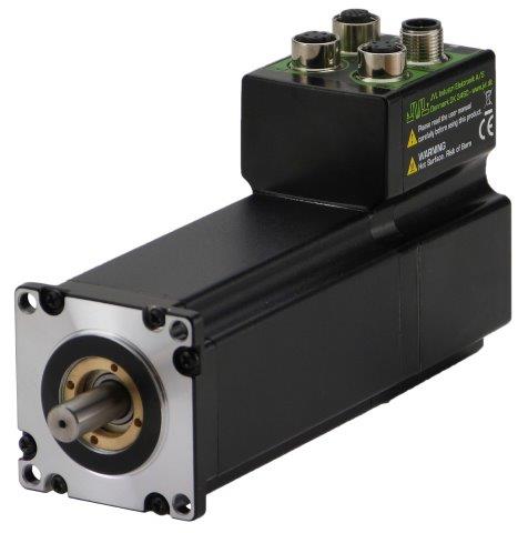
QuickStep, die integrierten ServoStep-Motoren von JVL.
Vielfältige Möglichkeiten mit einer NEMA23 -Baureihe kompakter Schrittmotoren mit höchster Mikroschrittauflösung, Closed-Loop-Betrieb, 3000 RPM und bis zu 3,08 Nm. Mit Standard-Schrittmotor oder neuer Hybrid-Schrittmotortechnologie erhältlich, die mit Seltenerdmagneten im Rotor bei gleicher Größe ein 40 % höheres Drehmoment ermöglicht.
Optional:
 |
|
 |
 |
 |
 |
 |
|||||
- Spezifikationen
- Abmessungen
- Anbindung
- Betriebsarten
- Kurven
| Drehmoment [Nm] |
Länge [mm] |
Welle [mm] |
Leistung Watt @72VDC | Gewicht [kg] |
Stecker |
|
| Hohes Drehmoment |
||||||
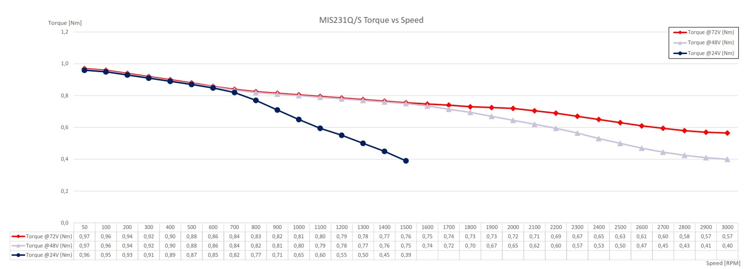
| MIS231Q |
0.97 |
103 ±1.0 | 6.35 |
95 |
1.1 |
Axial (hinten) |
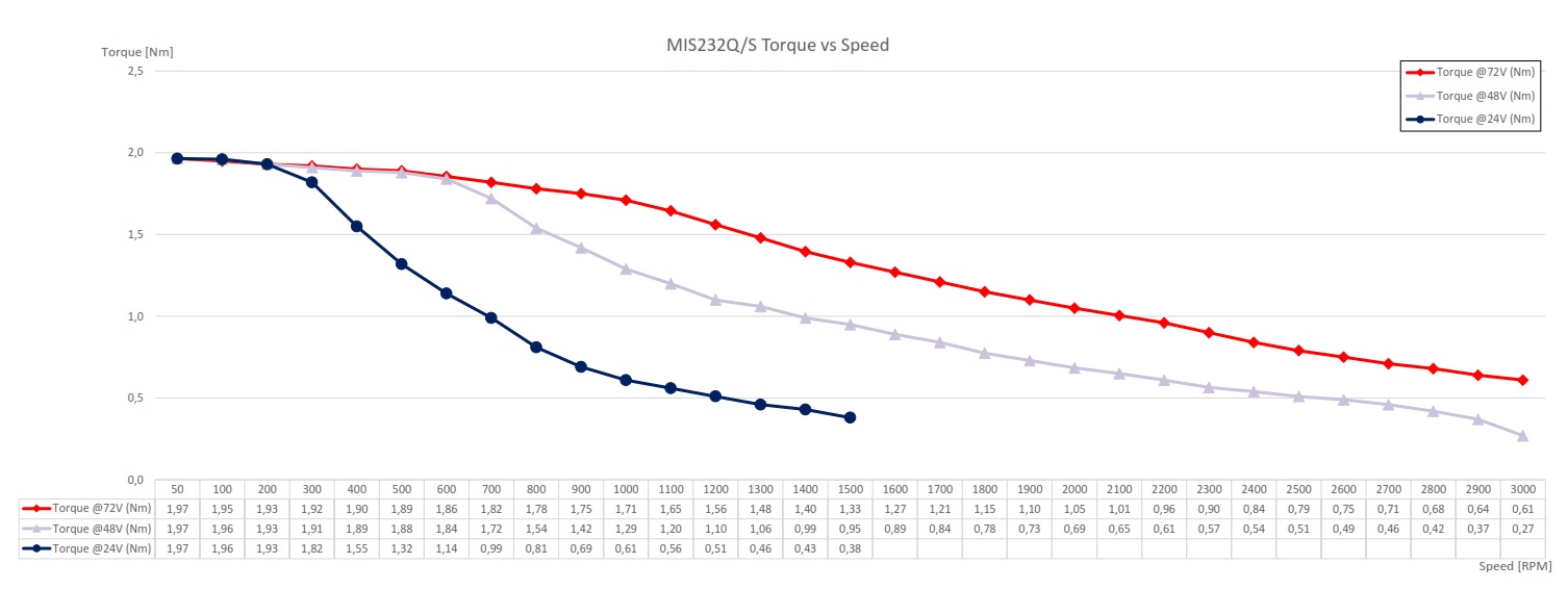
| MIS232Q |
1.97 |
124 ±1.0 |
6.35 |
125 |
1.4 |
Axial (hinten) |
| MIS234Q |
3.08 |
161 ±1.0 |
10.0 |
140 |
2.0 |
Axial (hinten) |
| MIS231S | 0.97 | 103 ±1.0 |
6.35 |
95 |
1.1 |
Radial (oben) |
| MIS232S |
1.97 | 124 ±1.0 |
6.35 |
125 |
1.4 |
Radial (oben) |
| MIS234S | 3.08 | 161 ±1.0 |
10.0 |
140 |
2.0 |
Radial (oben) |
| Ultra-hohes Drehmoment |
||||||
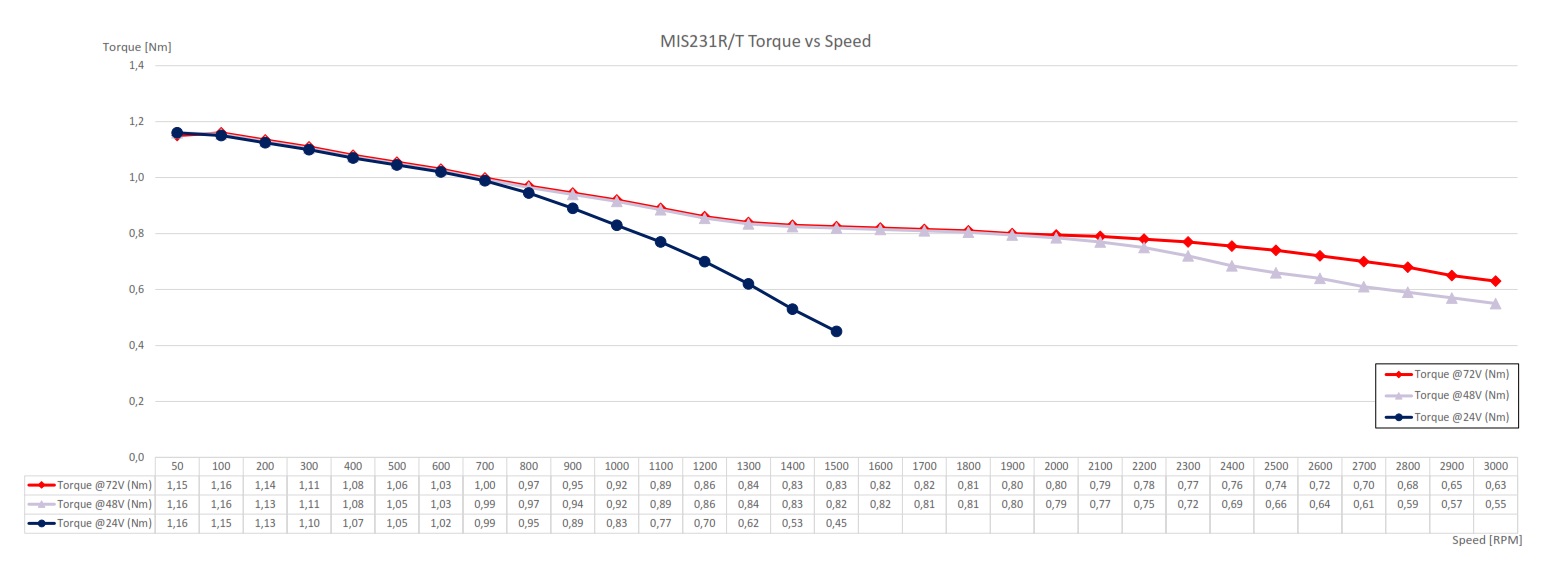
| MIS231R |
1.16 | 103 ±1.0 |
6.35 |
150 |
1.1 |
Axial (hinten) |
| MIS232R | 2.53 | 124 ±1.0 |
10.0 |
180 |
1.4 |
Axial (hinten) |
| MIS231T | 1.16 | 103 ±1.0 |
6.35 |
150 |
1.1 |
Radial (oben) |
| MIS232T | 2.53 | 124 ±1.0 |
10.0 |
180 |
1.4 |
Radial (oben) |
Industrial Ethernet und Closed-Loop Absolut-Multiturn-Encoder magnetische Rückführung (H4).
Wireless Ethernet ab Juni 2019 verfügbar.
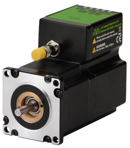
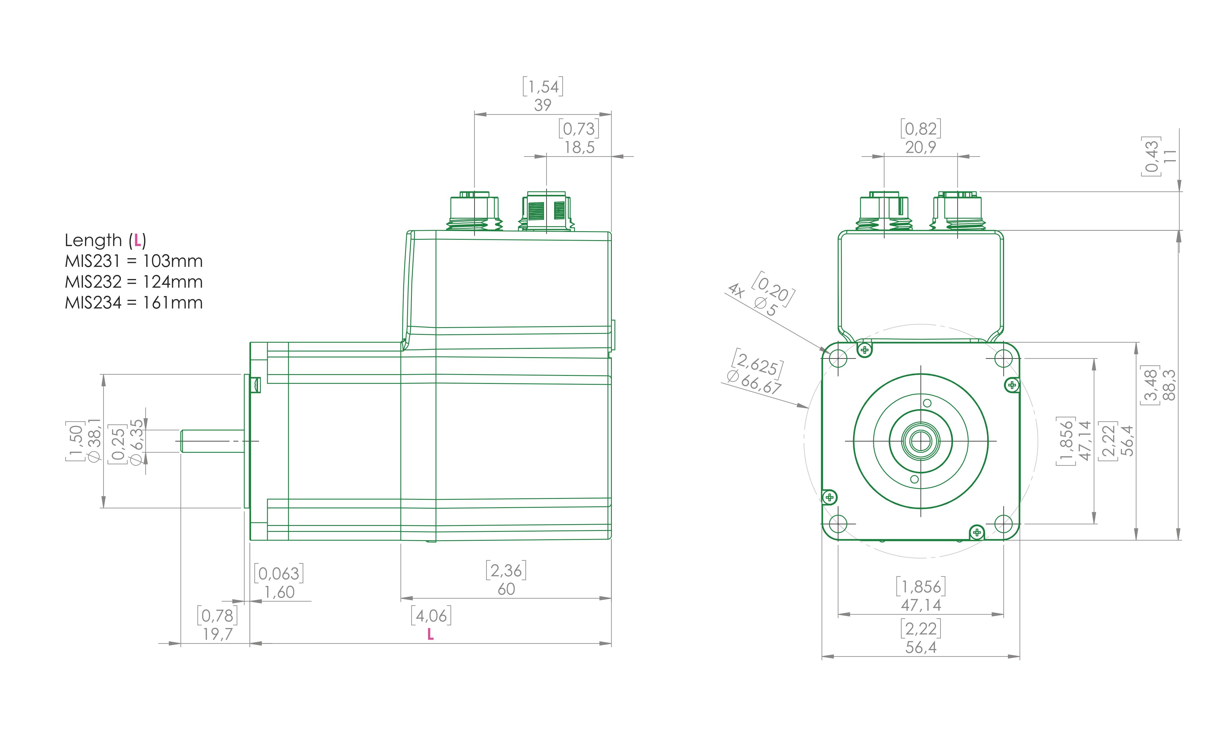
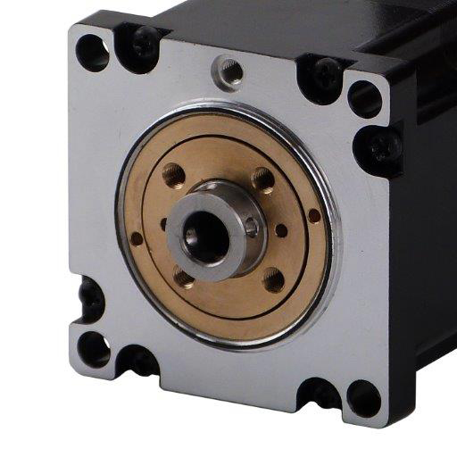
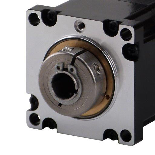
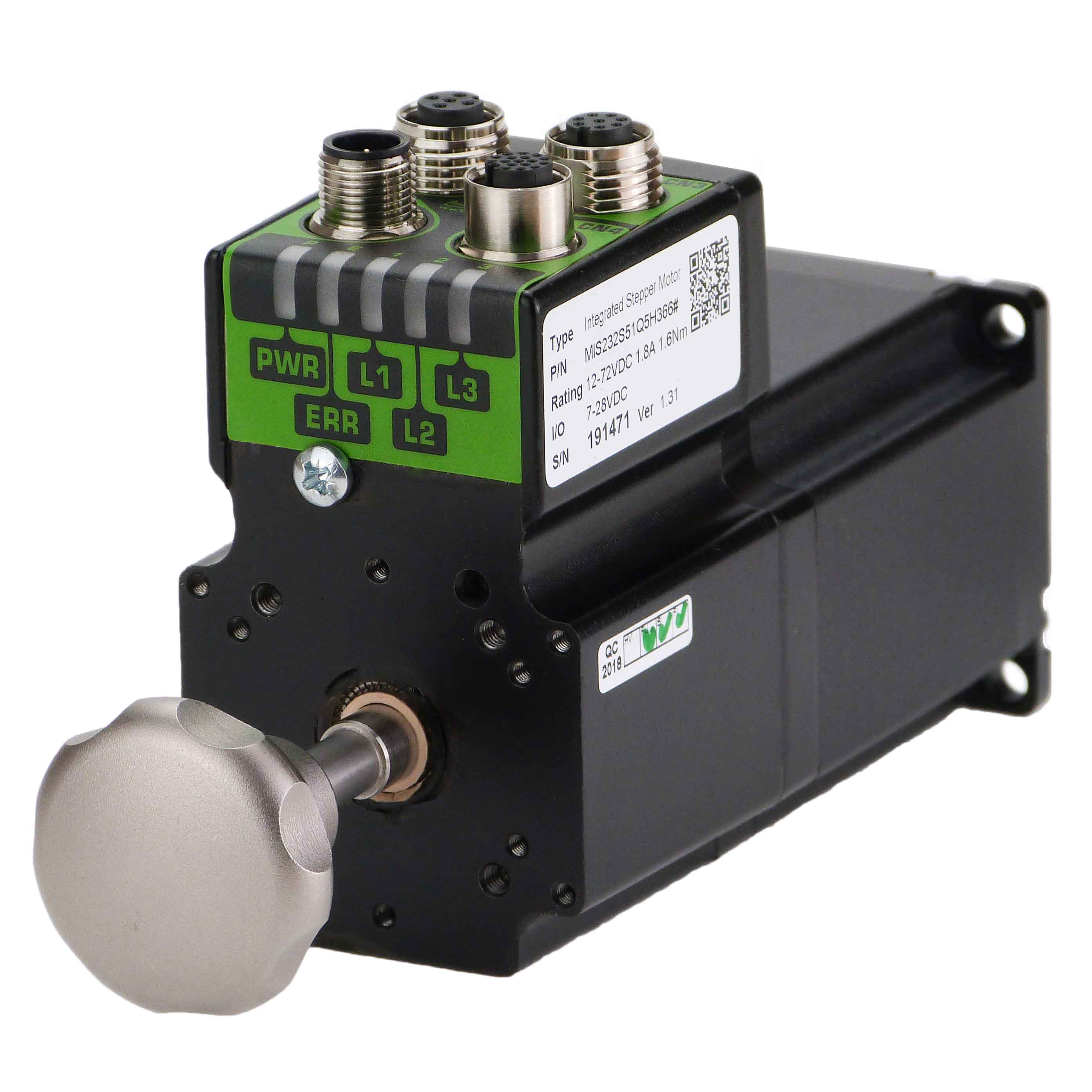
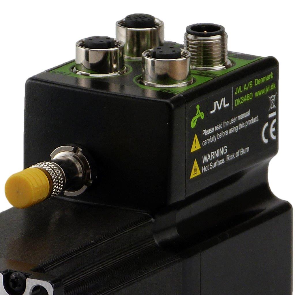
Alle mit 57x57mm Motorflansch. Standard M12-Stecker. Optional M23- oder kundenspezifischer Stecker hinten oder oben montiert.
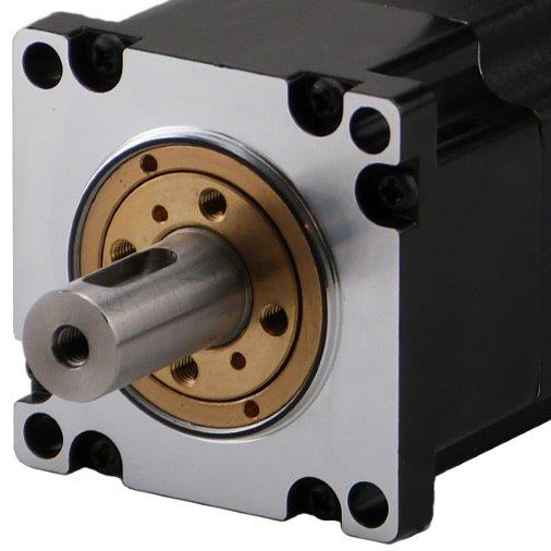
Welle aus Edelstahl AISI303 ist Standard für alle Modelle.
Alle mit 57x57mm Motorflansch. Standard M12-Stecker. Optional M23- oder kundenspezifischer Stecker hinten oder oben montiert.
Welle aus Edelstahl AISI303 ist Standard für alle Modelle.
Schrittmotor, Encoder und Elektronik wurden von JVL so entwickelt, dass sie eine geschlossene Einheit bilden, wobei Leistungstreiber, Controller, Ethernet und Wireless im Motor in einem geschlossenen Bereich mit einer Schutzart bis IP67 untergebracht sind. Alle Modelle sind standardmäßig mit Edelstahlwelle AISI303 ausgestattet.
| MIS23xS Abmessungen |
 |
| (Download) |
| QuickStep M12 Stecker Übersicht |
Power 5-pol. Buchse |
IO1-8 RS485 MFIO 17-polige Buchse |
RS485 5-polige Buchse |
RS485 + IO4 8-pol. Buchse |
CANopen 2x5-pol. Buchse |
SSI-Encoder 8-pol. Stecker |
Profibus 2x5-pol. Stecker B-Code |
Ethernet 2x4-pol. Stecker D-Code |
| MIS23xxyyQ5zz66 (Pre. Typ) |
X | X | X | X | ||||
| MIS23xxyyP6zz66 (CANopen) |
X | X | X | |||||
| MIS23xxyyQ9zz66 (SSI-Eingang) |
X | X | X | X | ||||
| MIS23xxyyExzz66 (Ethernet) |
X | X | X | |||||
| MIS23xxyyFBzz66 (Bluetooth) |
X | X | ||||||
| MIS23xxyyFPzz66 (Profibus) |
X | X | X | |||||
| MIS23xxyyExzz66 (Ethernet + SSI) |
X | X | x |
x |
||||
| M12 Pin 1 |
P+ (12-80VDC) |
IO1 | B0+ (RS485) |
IO1 | CAN_SHLD | IO5 Zero Set |
5VDC | TXO_P |
| M12 Pin 2 | P+ (12-80VDC) |
GND | A0- (RS485) |
IO2 | Unbenutzt | IO6 CNTDIR |
A- | RXO_P |
| M12 Pin 3 |
P- (GND) |
IO2 | B0+ (RS485) |
IO3 | CAN_GND | A+ (Clock+) |
DGND | TXO_N |
| M12 Pin 4 |
CVI (12-28VDC) |
IO3 | A0- (RS485) |
GND | CAN_H | GND | B+ | RXO_N |
| M12 Pin 5 |
P- (GND) |
B1- (RS422) |
GND | B0- (RS485) |
CAN_L | B- (Data in-) |
SHIELD | - |
| M12 Pin 6 |
- | IO4 | - | A0+ (RS485) |
- | B+ (Data in+) |
- | - |
| M12 Pin 7 |
- | A1- (RS422) |
- | IO4 | - | A- (Clock-) |
- | - |
| M12 Pin 8 |
- | B1+ (RS422) |
- | CVO (out) |
- | CVO (out) |
- | - |
| M12 Pin 9 |
- | CVO (out) |
- | - | - | - | - | - |
| M12 Pin 10 |
- | A1+ (RS422) |
- | - | - | - | - | - |
| M12 Pin 11 |
- | IO5 | - | - | - | - | - | - |
| M12 Pin 12 |
- | IO6 | - | - | - | - | - | - |
| M12 Pin 13 |
- | IO7 | - | - | - | - | - | - |
| M12 Pin 14 |
- | IO8 | - | - | - | - | - | - |
| M12 Pin 15 |
- | A0+ (RS485) |
- | - | - | - | - | - |
| M12 Pin 16 |
- | GND | - | - | - | - | - | - |
| M12 Pin 17 |
- | B0- (RS485) |
- | - | - |
- |
- |
- |
| M12 Stecker Lötanschlüsse |
WI1008-M12F5SS1 |
(nicht verfügbar) |
WI1008-M12M5SS1 |
WI1008-M12M8SS1 |
WI1008-M12M5SS1 | WI1008-M12FBSSI |
WI1028-M12F5SS1 | (nicht verfügbar) |
| M12 Kabel 5m. |
WI1000-M12F5T05N | WI1009-M12M17T05N |
WI1005-M12M8VM5V03N | WI1000-M12M8T05N |
WI1006-M12F5TM5T05N |
WI1000-M12F8T05N |
WI1026-M12F5S05R |
WI1046-M12M4S05R |
Choose between wireless Bluetooth, WLAN or Industrial Ethernet Profinet, Ethernet/IP, EtherCAT, Powerlink, MODBUS TCP/IP, SERCOS III, RS485 and PLC built-in are standard. 8IOA, SSI and pulse/direction
| Industrial Ethernet | Profinet, Ethernet/IP, EtherCAT, Powerlink, MODBUS TCP/IP, SERCOS III . Built in dual port Ethernet switch for simple wiring and cost reduction. | Read more |
| SSI (RS485) | Build in SSI interface for external incremental or absolute encoder. 5V balanced signals. | Read more |
| CANBUS | CANbus DS-301 with heartbeat/Node guarding/sync etc. | Read more |
| MODBUS (RS485) | RS485 interface for serial 2Mbit daisy chain communication for low cost solution. | Read more |
| MACTALK (RS485) | RS485 interface for live diagnostics, setup and user programming. | Read more |
| PLC | 8 input/output/analogue input allow highly advanced functions via the build in PLC. | Read more |
| Gear Mode (RS422) |
In this mode the QuickStep motor functions as in a step motor driver. The motor moves one step each time a voltage pulse is applied to the step-pulse input. Velocity, acceleration and deceleration are determined by the external frequency, but can be limited and controlled by the QuickStep motor. In addition, the QuickStep motor also provides a facility for electronic gearing at a keyed-in ratio. | |
| Serial Mode (RS485) |
In this mode the QuickStep motor’s registers contain the positions, velocities, accelerations, etc., required for the actual system. The registers can be selected and executed by a single byte sent via the serial interface. This mode provides maximum utilization of the QuickStep motor’s features since the QuickStep motor itself takes care of the entire positioning sequence. |
|
| Position and velocity Mode (RS485) |
With command sent over the serial interface can position and velocity be changed. Various operating parameters can be changed continuously while the motor is running. This mode of operation is used primarily in systems where the Controller is permanently connected to a PC/PLC via the interface. It is also well suited for setting up and testing. The mode is also used when programming is made. |
|
| Outputs | Up to 8 pcs high side for relay, PLC or brake control. 24VDC PNP high power 0,4A (peak 0,9A) each. Short circuit and reverse protected. | |
| Inputs | Up to 8 pcs 24VDC logic inputs that can we used for limit switch, homing, position capture, enable input, pulse/dir. | |
| Analogue input | Up to 8 pcs 0-5V 12bit that can we used in program for analogue to speed or position. Protected up to +-30VDC. | |
| RS422 | Input used for connection of external encoder, AB incremental signal or pulse and direction signal. 5VDC balanced signal A+.A-,B+.B- |
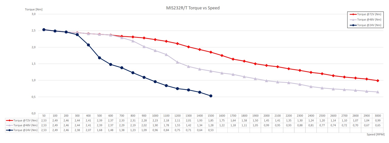
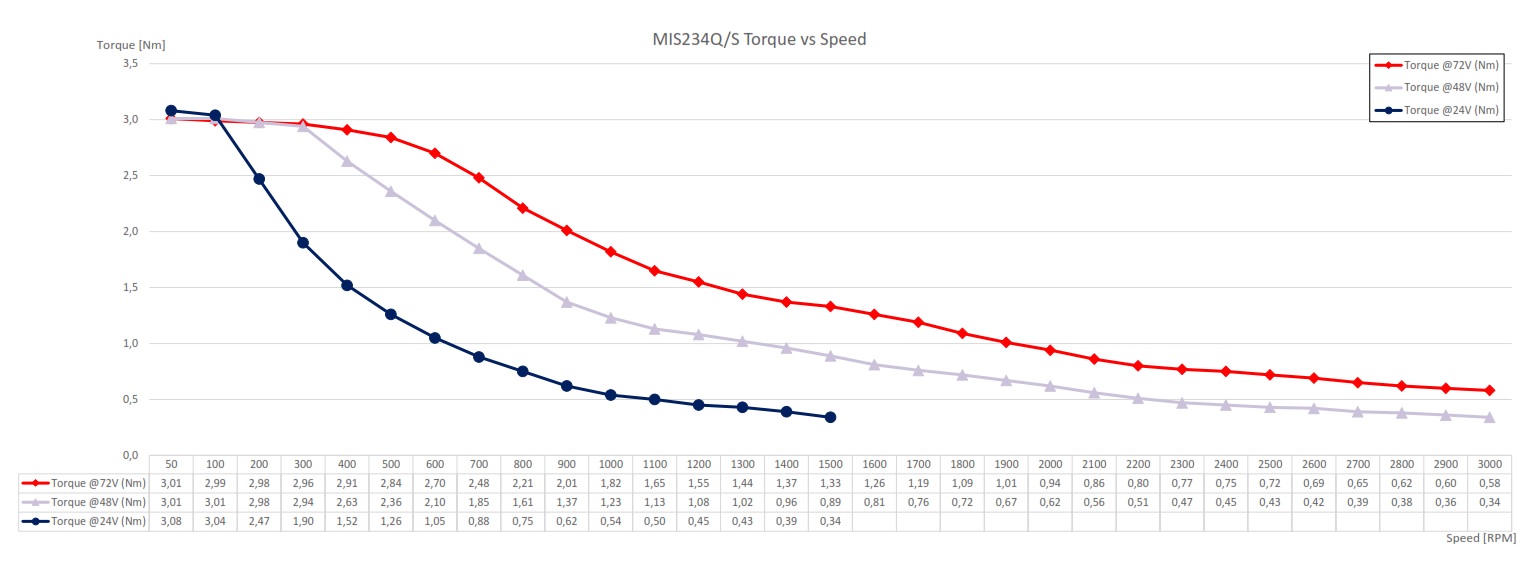
Alle Messungen erfolgen im Open-Loop-Modus der Motoren.
| MIS231Q/S Drehmoment/Leistung/Wirkungsgrad |
MIS231R/T Drehmoment/Leistung/Wirkungsgrad |
|
 |
 |
|
| (Download) |
(Download) |
| MIS232Q/S Drehmoment/Leistung/Wirkungsgrad |
MIS232R/T Drehmoment/Leistung/Wirkungsgrad |
|
 |
 |
|
| (Download) |
(Download) |
| MIS234Q/S Drehmoment/Leistung/Wirkungsgrad |
||
 |
||
| (Download) |
| Zum JVL YouTube-Channel |
|
| JVL Präsentationsvideo (vorläufig) | |
| JVL Akademie |
|
|
|
|
|
|
|
|
WEITERE EINZELHEITEN |
|
|
|
DOWNLOAD |


JVL A/S Deutschland Moltkestr. 24 DE-72762 Reutlingen Deutschland
Tel: +49 7121 1377260 Fax: +49 7121 1377317 E-mail: sales@jvl.dk
Tel: +49 7121 1377260 Fax: +49 7121 1377317 E-mail: sales@jvl.dk
